ASTM D638 The Essential Guide to Plastic Tensile Testing.

HOW TO PERFORM A TENSILE STRENGTH TEST ON PLASTICS ACCORDING TO ASTM D638

ASTM D638 is the most widely used testing standard for measuring the tensile properties of reinforced and non-reinforced polymers. With the use of plastics at an all-time high, producers must be able to accurately measure the mechanical strength of their products. This guide will introduce you to the fundamentals of an ASTM D638 plastic tensile test, including an overview of the equipment, software, and samples required. However, anyone wishing to do ASTM D638 testing should not use this advice as a substitute for reading the full standard.

WHAT DOES IT MEASURE?

ASTM D638 is conducted by applying a tensile force to a sample specimen and measuring its different properties while under stress. It is performed using a universal testing machine (also known as a tensile testing machine) at tensile rates ranging from 1 to 500 mm/min until the specimen fails (yields or breaks).
 
ASTM D638 measures several different tensile qualities, however the following are the most common:
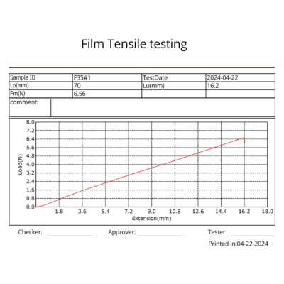
  • Tensile strength – the amount of force that can be applied to a plastic before it yields (stretches irreparably) or breaks.
  • Tensile modulus – how much a material can deform (stretch) in response to stress before it yields. Modulus is a measurement of the material’s stiffness.
  • Elongation – the increase in gauge length after break divided by the original gauge length. Greater elongation indicates higher ductility.
  • Poisson’s Ratio – a measurement of the relationship between how far a material is stretched and how thin it gets during the stretching process.

IS ASTM D638 THE RIGHT STANDARD FOR YOU?

There are numerous test procedures for different types of plastics. ASTM D638 only applies to stiff plastic samples measuring 1.00 mm to 14 mm in thickness. If your sample is a sheet or film less than 1.00 mm thick, it should be tested according to ASTM D882. While ASTM D638 yields similar results to ISO 527-2, it is not deemed technically equivalent due to changes in specimen size and test parameters. While some large international firms test to both ASTM D638 and ISO 527-2, the majority of our customers prefer one standard over the other based on geography. North American manufacturers typically test to ASTM D638, where those in Europe and Asia largely test to ISO 527-2. Customers in Malaysia test to both ASTM D638 and ISO 527-2. All of these test methods are available in EvoTest Software, which are pre-configured method templates for the most common ASTM and ISO standards.

MATERIALS TESTING SYSTEM

Most ASTM D638 testing is done on a tabletop universal testing machine like Victor VEW 2308E Series. The most typical capacity is 5 kN or 10 kN (1125 or 2250 lbf), although as the strength of reinforced plastics and composites increases, higher capacity units, may be required.

GRIPS

It is critical that specimens are secured firmly inside the tensile machine. Side action pneumatic grips with serrated jaw faces are frequently the best choice for grasping hard plastics. Pneumatic grips use air pressure to maintain gripping force, which remains constant even if the specimen thickness changes dramatically during the test. manual wedge action grips are suited for forces more than 10 kN, which are commonly found in reinforced materials.

SPECIMEN TYPES

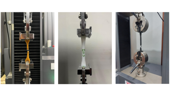
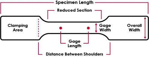
ASTM D638 allows five different specimen kinds, each with a different size based on the thickness of the specimen and the amount of available material. The most prevalent are Type I specimens, which are 3.2 mm thick and are often made by injection molding. Type I specimens had an overall length of 165 mm, a width of 13 mm, and a gauge of 50 mm. Flat specimens are usually molded, die-cut, or machined into a “dogbone” or “dumbbell” shape, ensuring that the break happens in the middle of the specimen rather than at the clamping points. In addition to flat specimens, ASTM D638 permits the testing of rigid tubes and rods, both of which must be machined into a dogbone shape. In cases where material is limited, many labs will employ Type IV or Type V samples. The dimensions necessary for Type IV specimens are identical to those required for ASTM D412 die cut C, hence the same die cut can be utilized. Type V specimens are the tiniest, with a gauge length of just 0.3 in.
 

SPECIMEN MEASUREMENT

All specimens must be measured before testing, in line with ASTM D5947. Most ordinary micrometers should be enough for these measurements. To display Stress values rather than only Force readings, operators will be requested to provide the specimen’s cross-sectional area (or thickness and width), because Stress = Force / Cross-Sectional Area (given in units of Psi, Pa, kPa, GPa, and so on).
 
Die-cut or machined samples must be measured individually, whereas operators utilizing injection molded specimens only need to measure one sample from a sample lot if the variation in that sample lot is less than 1%. Injection molded specimens are frequently manufactured with a draft angle rather than being precisely square, which must be considered while measuring the specimen. Always measure the breadth at the middle of the draft angle.

SPECIMEN ALIGNMENT

To ensure accurate testing, specimens must be kept perpendicular to the jaw faces and not slanted at an angle. Specimen misalignment can result in significant variances in results, hence sufficient care should be taken to ensure that all specimens are uniformly aligned for each test. One method for resolving misalignment is to use a jaw face that is around the same width as your specimen, making it reasonably simple to visually modify alignment. However, the simplest solution to avoid misalignment is to employ a specimen alignment device that mounts directly to the grip bodies. This is a basic bar with an adjustable stopping point, allowing operators to simply determine whether their specimen has been correctly aligned.
 
When the grips are tightened on the plastic specimens in preparation for a test, undesired compressive forces are frequently imposed. These forces, however minor, can interfere with test findings if not handled properly: It is critical that they not be balanced after the specimen has been placed, as this will result in an offset in results. 

EXTENSOMETERS FOR ELOGATION TESTS

The modulus of elasticity, or how much the specimen stretches or deforms in response to tensile force, is one of the most essential pieces of data collected by ASTM D638 plastic tensile testing. To collect this data, users will require an appropriate strain measurement instrument, such as an extensometer. Extensometers used to measure modulus must conform with ASTM E83 Class B-2.

CALCULATIONS AND RESULTS

When presenting test results, it is critical to ensure that the words are correctly specified in order to comply with the standard and permit data comparison between laboratories. The most common mistake in data reporting is to report strain values using an incorrect source (extensometer instead of crosshead) which can lead to drastically different results.

Plastic testing standards employ the phrase “nominal strain,” which is defined variably based on the test method utilized. For ASTM D638, nominal strain is defined as the strain measured from the crosshead displacement rather than the extensometer. This is because plastic does not degrade uniformly, and strain is sometimes concentrated on a disproportionately small section of the sample, a feature known as “necking”. For any materials that neck or have a yield point, the extensometer cannot indicate % elongation at break since necking may occur outside of the gauge length. As a result, nominal strain must be utilized when reporting percent elongation at any point after yield. Using an extensometer to measure strain at break is only acceptable if the strain is uniform across the specimen and does not display necking or yield.

MODULUS

Plastics with varying behaviors may necessitate the use of alternative modulus estimations to accurately capture the elastic component of the test. Most current testing software allows you to customize modulus calculations. Understanding how the modulus is computed is crucial to achieving consistent results.
 
For a material that lacks a genuine linear part, a secant modulus is often recommended, which creates a modulus line between zero and any user-defined curve point. Segment modulus calculations generate a best-fit line between a given start and end point and use a least-squares fit. A Young’s modulus calculation is most typically employed, with the slope determined over a number of locations and the steepest slope reported using a least-squares fit.

THROUGHPUT

For labs with high-volume testing requirements, numerous changes to the tensile machine configuration can be made to speed up the testing process and enhance throughput, including completely automated test systems. Fully automated systems include specimen measurement, loading, testing, and removal and can run for hours without operator intervention. These technologies serve to reduce variability due to human error and can be left running after a shift is completed to continue receiving findings when operators return home.

Leave a Reply

Your email address will not be published. Required fields are marked *